About this time of year I am often asked by friends who have children about the same age as my daughter "Which electronics kit should I buy for my child?"
A good question as there is a bewildering array of them out there a very quick search on Amazon brings back over a thousand results, and add to that ebay, other online sellers and the offerings of the high street toy shops and it becomes a huge number.
So - how to chose??
Well, You have to weigh up the level of experience your child has - if they are already past the basics and can solder then there is a wide range of specific purpose kits out there eg:
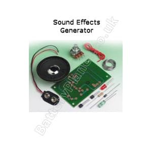 They are usually good value, Costing from a few pounds up to a few tens of pounds - (this particular one costs about £10 from here). Most of them are simple enough to get working and to stand some rough and ready assembly techniques. Lots to choose from - but look out for well made kits with good documentation. A personal favourite manufacturer is Vellman who generally seem one of the better manufacturers, though there are many.
But... The chances are that if your child is already advanced enough to be at this stage, they will be telling you what they want rather than leaving you guessing. While these sorts of kits are a good introduction to soldering, its also important to note that actually these sort of kits actually teach you very little about actual electronics - much the same way as painting by numbers teaches you little about painting. Its simply a case of finding the right component from the list and soldering it into the holes on the board. Few kits go beyond a hurried circuit diagram and do not properly explain any of the underlying workings of the circuit.
On the whole - great for those wanting to learn to solder, or for the more advanced builder , but best to avoid if your child is a newcomer to electronics
Instead, aim for a multi project kit which includes good learning materials teaching the basics of electronic circuit design in a progressive way - what is generally though of as an "electronics kit" rather than a "project".
Of these, what I call the "wire - spring linkup " electronics kits are by far the most common.
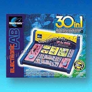
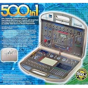 They range from small, inexpensive kits with a limited number of options such as this one shown on the left, to very comprehensive kits similar to the one shown on the right which can cost hundreds of pounds
I call them the "wire - spring linkup" type because of the way you construct the circuits you are building. The components themselves are in fixed locations within the kit and to join them together you link them together by trapping the ends of insulated wires in spring loaded terminals which each component is equipped with.
These kits generally offer great value for money - though the maxim about getting what you pay for is still applicable. The better ones generally cover the basic fundamentals of electronics - the beginnings of ohms law, how components work and how they relate to each other to make a circuit. The more comprehensive ones have some interesting circuits too - which is important as your child will want to see something useful at the end of all that wire linking.
They do however have a downside. Because the components are in fixed locations on the board, when you are linking them up, the resulting rats nest of wires will have no resemblance to the circuit diagram you are following. Fault finding can be difficult, and generally understanding what is going on is much harder.
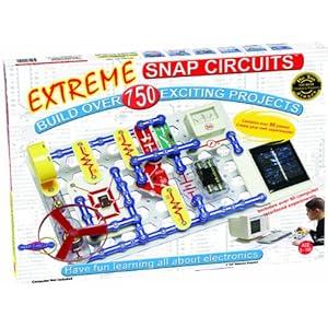
If I personally had to chose a particular type of kit to recommend overall, it would be one like this:

Why?? Well it comes down simply to this, you lay out the components and the links between them EXACTLY as it looks in the circuit diagram:

Brilliant!!
There are a range if kits by Snap Circuits, and other manufactures of this type ranging from a few tens of pounds up to a few hundreds .
While I cant comment on other manufacturers, the manuals produced in the genuine Snap Circuits kits are some of the best I have ever seen and closely follow the learning work which my daughter does at school. They are designed to be used by both learner and tutor - which is important as you will be taking a semi-active roll in helping your child with this right?? ;)
NB: links and images are not intended to endorse any particular product / supplier - they are just the most convenient way of illustrating this post - if any manufactures / suppliers object to my use of their images etc please leave me a message and I will edit accordingly.
A good question as there is a bewildering array of them out there a very quick search on Amazon brings back over a thousand results, and add to that ebay, other online sellers and the offerings of the high street toy shops and it becomes a huge number.
So - how to chose??
Well, You have to weigh up the level of experience your child has - if they are already past the basics and can solder then there is a wide range of specific purpose kits out there eg:
But... The chances are that if your child is already advanced enough to be at this stage, they will be telling you what they want rather than leaving you guessing. While these sorts of kits are a good introduction to soldering, its also important to note that actually these sort of kits actually teach you very little about actual electronics - much the same way as painting by numbers teaches you little about painting. Its simply a case of finding the right component from the list and soldering it into the holes on the board. Few kits go beyond a hurried circuit diagram and do not properly explain any of the underlying workings of the circuit.
On the whole - great for those wanting to learn to solder, or for the more advanced builder , but best to avoid if your child is a newcomer to electronics
Instead, aim for a multi project kit which includes good learning materials teaching the basics of electronic circuit design in a progressive way - what is generally though of as an "electronics kit" rather than a "project".
Of these, what I call the "wire - spring linkup " electronics kits are by far the most common.
They range from small, inexpensive kits with a limited number of options such as this one shown on the left, to very comprehensive kits similar to the one shown on the right which can cost hundreds of poundsI call them the "wire - spring linkup" type because of the way you construct the circuits you are building. The components themselves are in fixed locations within the kit and to join them together you link them together by trapping the ends of insulated wires in spring loaded terminals which each component is equipped with.

They do however have a downside. Because the components are in fixed locations on the board, when you are linking them up, the resulting rats nest of wires will have no resemblance to the circuit diagram you are following. Fault finding can be difficult, and generally understanding what is going on is much harder.
If I personally had to chose a particular type of kit to recommend overall, it would be one like this:
Why?? Well it comes down simply to this, you lay out the components and the links between them EXACTLY as it looks in the circuit diagram:
Brilliant!!
There are a range if kits by Snap Circuits, and other manufactures of this type ranging from a few tens of pounds up to a few hundreds .
While I cant comment on other manufacturers, the manuals produced in the genuine Snap Circuits kits are some of the best I have ever seen and closely follow the learning work which my daughter does at school. They are designed to be used by both learner and tutor - which is important as you will be taking a semi-active roll in helping your child with this right?? ;)
NB: links and images are not intended to endorse any particular product / supplier - they are just the most convenient way of illustrating this post - if any manufactures / suppliers object to my use of their images etc please leave me a message and I will edit accordingly.


